Using Alternative Carrier Gases with Accelerated ASTM D2887 Simulated Distillation Analysis

Introduction
ASTM Method D2887 is a widely used test procedure for simulated distillation (SimDist) analysis. This method is applicable to petroleum fractions with a final boiling point between 55 °C and 538 °C at atmospheric pressure and with vapor pressures that allow sampling at ambient temperatures. ASTM D2887 is used to evaluate process stream samples in order to provide accurate data for optimizing refinery operations, and it can also be used for product specification testing as allowed by contractual agreements. Most often, the method is run using a wide-bore (0.53 mm ID) column with a 0.88 to 2.65 µm polydimethylsiloxane (PDMS) layer. Thick-film columns offer more sample loading capacity and are preferred over traditional packed columns because of their comparatively low-bleed characteristic and reduced analysis times.
Method D2887 includes an accelerated option (procedure B) for use when faster analyses are desired. Recently, the method also included an allowance for alternate carrier gases so that the standard helium carrier gas can be replaced with either hydrogen or nitrogen. Using these alternate carrier gases allows companies to take advantage of significant cost savings and to employ reliable and more easily available carrier gases. The easiest way to switch carrier gases is to use method translation, which is well known to preserve elution order and compound separation. An interesting derivative of method translation can be used to preserve retention times. Here, our approach was to translate the original method to alternative carrier gases so that the original retention times would be maintained. We show that with an MXT-1HT SimDist column and Restek’s EZGC online method translator, existing methods based on helium carrier gas can be easily converted to either hydrogen or nitrogen carrier gas without sacrificing the accuracy of the method. Because retention times are preserved with proper method translation, there are minimal changes to peak identification tables and method validation is a much simpler task.
How to Match Your Helium Method
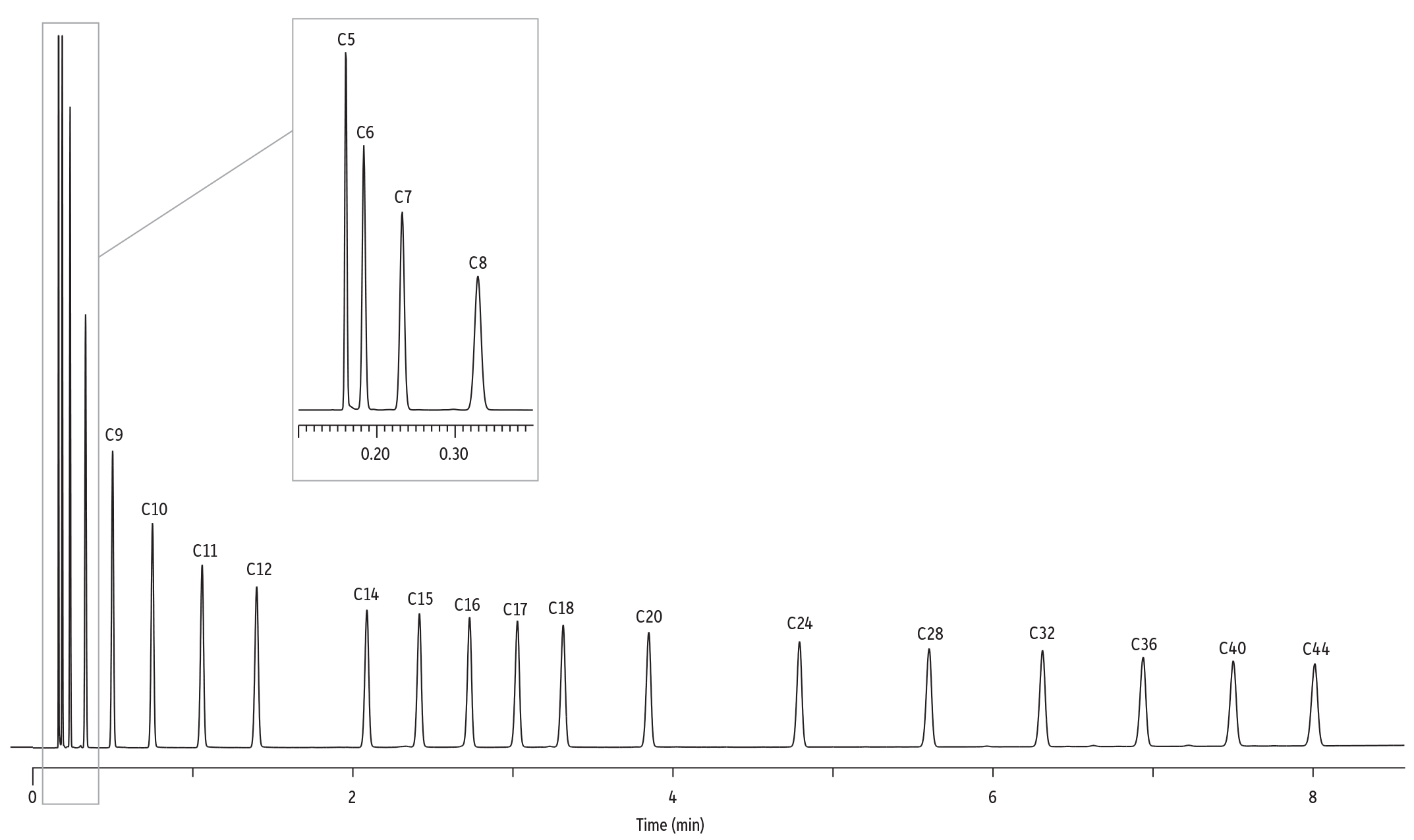
Helium carrier gas is traditionally used for ASTM D2887 because it is nonflammable and gives good resolution at an acceptably fast flow rate. However, helium is expensive and it can fluctuate in availability. Using methodology based on the accelerated parameters (procedure B) for helium carrier gas, along with an MXT-1HT SimDist column, provided very good chromatographic results (Figure 1). Requirements for resolution and skewness were met. In addition, excellent linearity was obtained for the C10-C44 calibration curve of retention time versus boiling point. Note that to extend the linearity of the curve down to C5, the initial column temperature can be lowered to subambient temperatures, or a thicker film column (2.65 µm) can be used.
Figure 1: Excellent chromatographic results for accelerated SimDist analysis (ASTM D2887, procedure B) are obtained using an MXT-1HT SimDist column and helium carrier gas.
| Column | MXT-1HT SimDist, 10 m, 0.53 mm ID, 0.88 µm (cat.# 70134) |
| Sample | ASTM D2887-12 calibration standard (cat.# 31674) |
| Injection | |
| Inj. Vol.: | 0.02 µL cool on-column |
| Temp. Program: | 100 °C to 360 °C at 35 °C/min |
| Oven | |
| Oven Temp.: | 60 °C to 360 °C at 35 °C/min |
| Carrier Gas | He, constant flow |
| Flow Rate: | 26 mL/min |
| Detector | FID @ 360 °C |
| Make-up Gas Flow Rate: | 20 mL/min |
| Make-up Gas Type: | N2 |
| Hydrogen flow: | 40 mL/min |
| Air flow: | 360 mL/min |
| Instrument | Agilent 7890B GC |
| Notes | Accelerated analysis based on ASTM Method D2887 (Procedure B) |
Both hydrogen and nitrogen are attractive alternatives to helium carrier gas because they are less costly and readily available. In fact, both gases can easily be generated in-house, and many labs opt to use a hydrogen or nitrogen generator so they are assured of a reliable and cost-effective supply. In order to match the results obtained with helium when using hydrogen or nitrogen, we used Restek’s EZGC online method translator to adjust method parameters. This free, online software allowed us to easily establish instrument conditions that would give equivalent chromatographic results using either hydrogen or nitrogen carrier gases. Figure 2 shows the interface of the tool as well as the translated conditions for hydrogen and nitrogen.
Figure 2: Simplify the switch to hydrogen or nitrogen by using Restek’s EZGC online method translation software to establish conditions that produce the same oven parameters, analysis times, and chromatographic results.
Performance of Hydrogen Carrier Gas
Hydrogen is a good alternative carrier gas because you can use higher linear velocities while still obtaining adequate efficiency and, thus, resolution (Figure 3). Usually, fast SimDist methods use much higher linear velocities (>100 cm/sec) than are used in methods that focus on obtaining high-resolution separations. These high linear velocities are well beyond the optimal range for all carrier gases, but there is less efficiency loss with hydrogen than with either helium or nitrogen. Further, the drop in resolution at high linear velocities is much more subtle than the drop in efficiency. The reason the resolution differences are not as dramatic as Van Deemter plots would predict is that resolution is a function of the square root of efficiency.
Figure 3: Hydrogen carrier gas offers greater efficiency at the fast linear velocities (>100 cm/sec) that are typically used in fast simulated distillation.
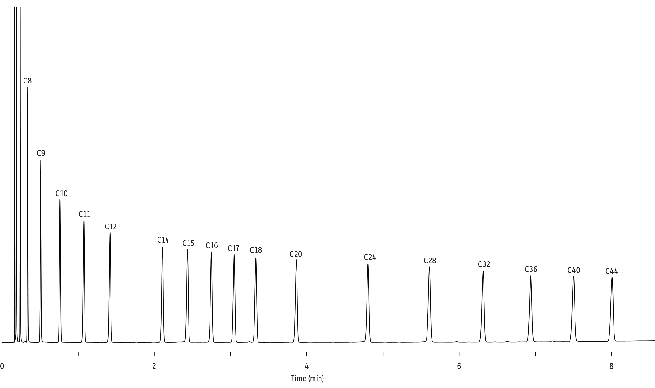
Using the EZGC method translator, conditions were established for hydrogen carrier gas that would give the same retention times as when using helium carrier gas. A partial validation was performed to evaluate the performance of hydrogen as an alternate carrier gas. The data for a retention time calibration standard in Figure 4 and Table I demonstrate that excellent results were obtained even at the 150 cm/sec linear velocity used in the accelerated section of ASTM Method D2887 (procedure B). Peak relative response factors all had a deviation of <10%, as specified in the method. In addition, peak shapes were very good with asymmetry values ranging from 0.96 to 1.19. Note that the translated conditions generated by the EZGC software provided virtually identical retention times compared to those obtained using helium.
Figure 4: Analysis of a retention time calibration standard using hydrogen carrier gas and translated method parameters established by EZGC online software.
| Column | MXT-1HT SimDist, 10 m, 0.53 mm ID, 0.88 µm (cat.# 70134) |
|---|---|
| Standard/Sample | ASTM D2887-12 calibration standard (cat.# 31674) |
| Injection | |
| Inj. Vol.: | 0.02 µL cool on-column |
| Temp. Program: | 80 °C to 360 °C at 35 °C/min |
| Oven | |
| Oven Temp.: | 60 °C to 360 °C at 35 °C/min |
| Carrier Gas | H2, constant flow |
| Flow Rate: | 22.35 mL/min |
| Detector | FID @ 360 °C |
|---|---|
| Make-up Gas Flow Rate: | 30 mL/min |
| Make-up Gas Type: | N2 |
| Hydrogen flow: | 30 mL/min |
| Air flow: | 400 mL/min |
| Instrument | Agilent 7890B GC |
| Notes | Accelerated analysis based on ASTM Method D2887 (Procedure B) |
Table I: Evaluation of retention time calibration standard peak shapes and relative response factors when using hydrogen carrier gas.
| Carbon Number | % Mass | Asymmetry | Response Factor | Response Factor Deviation |
|---|---|---|---|---|
| C5 | 5.0 | - | - | - |
| C6 | 5.0 | 0.98 | 0.95 | 5% |
| C7 | 5.0 | 1.09 | 1.01 | -1% |
| C8 | 5.0 | 1.01 | 1.01 | -1% |
| C9 | 5.0 | 0.98 | 1.01 | -1% |
| C10 | 5.0 | 1.00 | 1.00 | 0% |
| C11 | 5.0 | 0.98 | 0.99 | -1% |
| C12 | 5.0 | 0.97 | 0.98 | 2% |
| C14 | 5.0 | 0.96 | 0.94 | 6% |
| C15 | 5.0 | 0.97 | 0.95 | 5% |
| C16 | 5.0 | 0.98 | 0.94 | 6% |
| C17 | 5.0 | 0.98 | 0.94 | 6% |
| C18 | 5.0 | 0.99 | 0.93 | 7% |
| C20 | 5.0 | 0.97 | 0.92 | 8% |
| C24 | 5.0 | 1.03 | 0.98 | 2% |
| C28 | 5.0 | 1.19 | 1.01 | -1% |
| C32 | 5.0 | 0.98 | 0.97 | 3% |
| C36 | 5.0 | 1.00 | 0.97 | 3% |
| C40 | 5.0 | 1.01 | 0.96 | 4% |
| C44 | 5.0 | 1.05 | 0.96 | 4% |
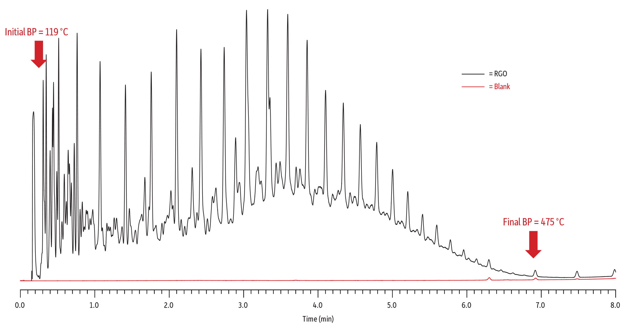
In addition to evaluation of a retention time standard, a blank and reference gas oil (RGO) were also analyzed. The overlay in Figure 5 shows the method requirement was met in that the blank chromatogram does not cross the sample chromatogram, even toward the end of the run. The boiling point distribution data (Table II) were also assessed using SimDist software. The SimDist software establishes a correlation between the boiling points of the hydrocarbons and their retention times in the chromatogram (Figure 1). Based on this calibration, RGO boiling point values at different offsets from the initial boiling point are calculated and compared to the RGO reported values (Table II). The results obtained from the translated SimDist method using hydrogen agree with the ASTM D2887 consensus boiling point values within the allowable percent of windows.
Figure 5: Overlay of blank and reference gas oil analyses show the stable baseline obtained using hydrogen carrier gas. Even at the end of the run, the blank chromatogram does not exceed the sample chromatogram.
| Column | MXT-1HT SimDist, 10 m, 0.53 mm ID, 0.88 µm (cat.# 70134) |
|---|---|
| Standard/Sample | ASTM D2887 reference gas oil 1, lot 2 |
| Diluent: | CS2 |
| Conc.: | 1% vol/vol |
| Injection | |
| Inj. Vol.: | 0.25 µL cool on-column |
| Temp. Program: | 80 °C to 360 °C at 35 °C/min |
| Oven | |
| Oven Temp.: | 60 °C to 360 °C at 35 °C/min |
| Carrier Gas | H2, constant flow |
| Flow Rate: | 22.35 mL/min |
| Detector | FID @ 360 °C |
|---|---|
| Make-up Gas Flow Rate: | 30 mL/min |
| Make-up Gas Type: | N2 |
| Hydrogen flow: | 30 mL/min |
| Air flow: | 400 mL/min |
| Instrument | Agilent 7890B GC |
| Notes | Accelerated analysis based on ASTM Method D2887 (Procedure B) |
Table II: Comparison of reference gas oil analyzed using hydrogen carrier gas to allowable values.
| ASTM D2887 Values | Observed Values | ||||
| %Offset | RGO Standard BP Temp. (°C) | Allowable Difference (°C) | Actual Measured BP Temp. (°C) | Difference (Measured Value - Standard Value) | Result |
| IBP | 115.6 | 7.6 | 119.4 | 3.8 | Pass |
| 5 | 151.1 | 3.8 | 151.2 | 0.1 | Pass |
| 10 | 175.6 | 4.1 | 178.6 | 3.0 | Pass |
| 15 | 200.6 | 4.5 | 204.2 | 3.6 | Pass |
| 20 | 223.9 | 4.8 | 227.4 | 3.5 | Pass |
| 30 | 259.4 | 4.7 | 262.4 | 3.0 | Pass |
| 40 | 288.9 | 4.3 | 291.2 | 2.3 | Pass |
| 50 | 312.2 | 4.3 | 313.1 | 0.9 | Pass |
| 60 | 331.7 | 4.3 | 331.3 | -0.4 | Pass |
| 65 | 342.8 | 4.3 | 343.1 | 0.3 | Pass |
| 70 | 353.3 | 4.3 | 354.0 | 0.7 | Pass |
| 75 | 365.6 | 4.3 | 365.9 | 0.3 | Pass |
| 80 | 377.8 | 4.3 | 378.4 | 0.6 | Pass |
| 85 | 391.1 | 4.3 | 391.2 | 0.1 | Pass |
| 90 | 406.7 | 4.3 | 407.5 | 0.8 | Pass |
| 95 | 428.3 | 5.0 | 429.9 | 1.6 | Pass |
| FBP | 475.6 | 11.8 | 475.2 | -0.4 | Pass |
Performance of Nitrogen Carrier Gas
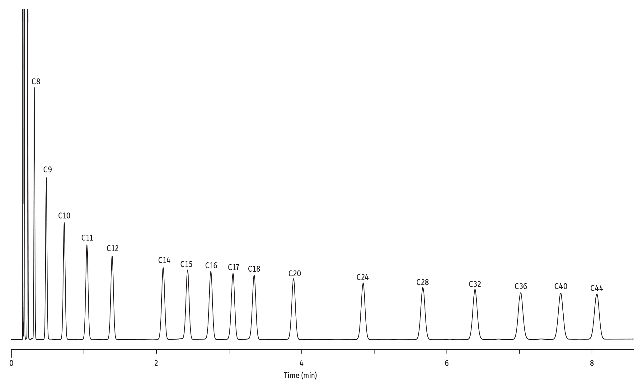
A potential drawback to using hydrogen carrier gas is that it is an explosive gas and safety can be a concern if it is not handled properly. Nitrogen can also be used as a carrier gas and some people prefer it because of its nonexplosive properties and affordability. Additionally, reliable nitrogen generators can now be purchased at a relatively low cost. The only drawback to nitrogen is its slow optimal linear velocity. Although the linear velocity used for accelerated SimDist analysis significantly exceeds the optimum level for nitrogen (as well as the optimum level for the other carrier gases), good chromatographic separations were still obtained (Figure 6). Peak width is broader under nitrogen due to the relatively large loss of efficiency, but resolution between target hydrocarbons is still well within the method parameters, and retention times were virtually identical to those obtained using helium carrier gas. Furthermore, the results reported in Table III demonstrate the excellent performance of the method in terms of response factor and peak asymmetry.
Figure 6: Analysis of a retention time calibration standard using nitrogen carrier gas and translated method parameters established by EZGC online software.
| Column | MXT-1HT SimDist, 10 m, 0.53 mm ID, 0.88 µm (cat.# 70134) |
|---|---|
| Standard/Sample | ASTM D2887-12 calibration standard (cat.# 31674) |
| Injection | |
| Inj. Vol.: | 0.015 µL cool on-column |
| Temp. Program: | 80 °C to 360 °C at 35 °C/min |
| Oven | |
| Oven Temp.: | 60 °C to 360 °C at 35 °C/min |
| Carrier Gas | N2, constant flow |
| Flow Rate: | 25.5 mL/min |
| Detector | FID @ 360 °C |
|---|---|
| Make-up Gas Flow Rate: | 20 mL/min |
| Make-up Gas Type: | N2 |
| Hydrogen flow: | 40 mL/min |
| Air flow: | 360 mL/min |
| Instrument | Agilent 7890B GC |
| Notes | Accelerated analysis based on ASTM Method D2887 (Procedure B) |
Table III: Evaluation of retention time calibration standard peak shapes and relative response factors when using nitrogen carrier gas.
| Carbon Number | % Mass | Asymmetry | Response Factor | Response Factor Deviation |
|---|---|---|---|---|
| C5 | 5.0 | - | - | - |
| C6 | 5.0 | 1.15 | 0.95 | 5% |
| C7 | 5.0 | 1.05 | 0.99 | 1% |
| C8 | 5.0 | 1.01 | 0.99 | 1% |
| C9 | 5.0 | 1.01 | 0.99 | 1% |
| C10 | 5.0 | 1.0 | 1.00 | 0% |
| C11 | 5.0 | 1.01 | 0.99 | 1% |
| C12 | 5.0 | 1.01 | 0.99 | 1% |
| C14 | 5.0 | 1.02 | 0.96 | 4% |
| C15 | 5.0 | 0.97 | 0.98 | 2% |
| C16 | 5.0 | 0.99 | 0.98 | 2% |
| C17 | 5.0 | 0.98 | 0.98 | 2% |
| C18 | 5.0 | 0.98 | 0.98 | 2% |
| C20 | 5.0 | 1.04 | 0.97 | 3% |
| C24 | 5.0 | 1.05 | 0.97 | 3% |
| C28 | 5.0 | 1.10 | 0.97 | 3% |
| C32 | 5.0 | 1.05 | 0.98 | 2% |
| C36 | 5.0 | 1.15 | 0.98 | 3% |
| C40 | 5.0 | 1.11 | 0.98 | 2% |
| C44 | 5.0 | 1.03 | 0.97 | 3% |
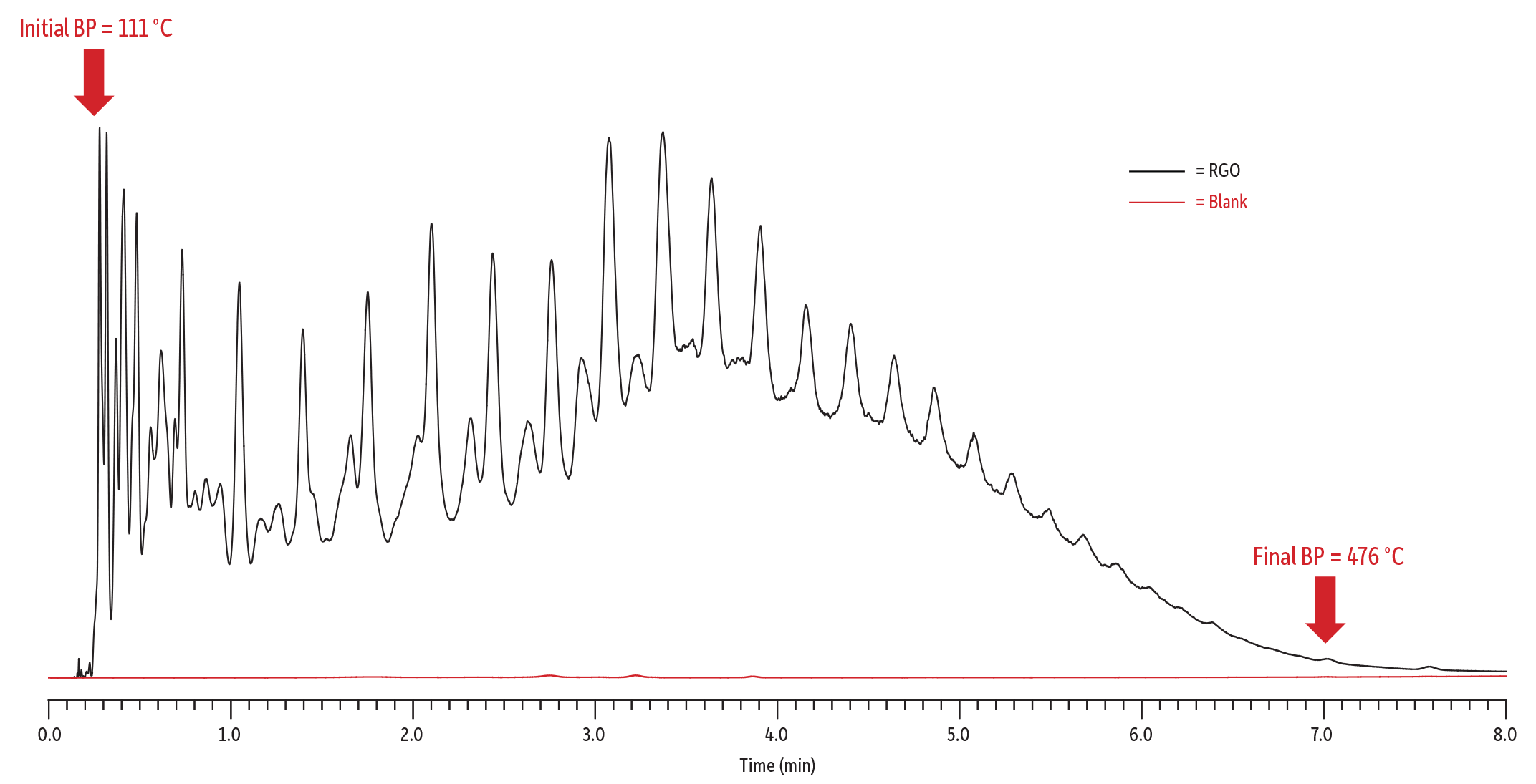
As with the hydrogen carrier gas experiment, a blank and reference gas oil were also analyzed using nitrogen carrier gas and the method parameters established for nitrogen using EZGC method translation software. Figure 7 shows the chromatographic overlay of the reference gas oil and the blank when using nitrogen carrier gas. As was the case with helium and hydrogen, good chromatographic results were obtained as indicated by the lack of overlap between the blank and the RGO. Further, the quantitative data obtained using SimDist software in Table IV show that the use of nitrogen carrier gas still produced boiling point values that met method requirements.
Figure 7: Overlay of blank and reference gas oil analyses show the stable baseline obtained using nitrogen carrier gas. No overlap is seen between the blank and RGO chromatograms.
| Column | MXT-1HT SimDist, 10 m, 0.53 mm ID, 0.88 µm (cat.# 70134) |
|---|---|
| Standard/Sample | ASTM D2887 reference gas oil 1, lot 2 |
| Diluent: | Neat |
| Injection | |
| Inj. Vol.: | 0.015 µL cool on-column |
| Temp. Program: | 90 °C to 360 °C at 35 °C/min |
| Oven | |
| Oven Temp.: | 60 °C to 360 °C at 35 °C/min |
| Carrier Gas | N2, constant flow |
| Flow Rate: | 25.5 mL/min |
| Detector | FID @ 360 °C |
|---|---|
| Make-up Gas Flow Rate: | 20 mL/min |
| Make-up Gas Type: | N2 |
| Hydrogen flow: | 40 mL/min |
| Air flow: | 360 mL/min |
| Instrument | Agilent 7890B GC |
| Notes | Accelerated analysis based on ASTM Method D2887 (Procedure B) |
Table IV: Comparison of reference gas oil analyzed using nitrogen carrier gas to allowable values.
| ASTM D2887 Values | Observed Values | ||||
|---|---|---|---|---|---|
| %Offset | RGO Standard BP Temp. (°C) | Allowable Difference (°C) | Actual Measured BP Temp. (°C) | Difference (Measured Value - Standard Value) | Result |
| IBP | 115.6 | 7.6 | 111.4 | -4.2 | Pass |
| 5 | 151.1 | 3.8 | 151.1 | 0.0 | Pass |
| 10 | 175.6 | 4.1 | 178.1 | 2.5 | Pass |
| 15 | 200.6 | 4.5 | 204.0 | 3.4 | Pass |
| 20 | 223.9 | 4.8 | 227.4 | 3.5 | Pass |
| 30 | 259.4 | 4.7 | 262.7 | 3.3 | Pass |
| 40 | 288.9 | 4.3 | 291.8 | 2.9 | Pass |
| 50 | 312.2 | 4.3 | 313.7 | 1.5 | Pass |
| 60 | 331.7 | 4.3 | 332.0 | 0.3 | Pass |
| 65 | 342.8 | 4.3 | 343.3 | 0.5 | Pass |
| 70 | 353.3 | 4.3 | 354.8 | 1.5 | Pass |
| 75 | 365.6 | 4.3 | 366.9 | 1.3 | Pass |
| 80 | 377.8 | 4.3 | 379.3 | 1.5 | Pass |
| 85 | 391.1 | 4.3 | 392.6 | 1.5 | Pass |
| 90 | 406.7 | 4.3 | 409.8 | 3.1 | Pass |
| 95 | 428.3 | 5.0 | 431.6 | 3.3 | Pass |
| FBP | 475.6 | 11.8 | 473.6 | -2.0 | Pass |
In Summary
ASTM Method D2887 was modified to include the use of alternative carrier gases. Companies running simulated distillation analyses now have the opportunity to use either hydrogen or nitrogen carrier gas, both of which are inexpensive and easy to produce in-house using a generator. When replacing helium carrier gas with either of these alternatives, revalidation and recalibration can be significantly simplified by using EZGC method translation software to establish method parameters that give equivalent retention times. Figure 8 directly compares the retention times for C5-C44 hydrocarbons that were presented earlier in the article. When viewed side by side, it is easy to see that the new parameters provided equivalent retention times for all three carrier gases. As would be expected, peaks are sharpest when using hydrogen and widest when using nitrogen; however, all three carrier gases perform well and provide an opportunity for companies to run accelerated SimDist testing to assure product quality and to optimize operations using less expensive and readily available carrier gases.
Figure 8: Comparison of ASTM D2887-B using helium, hydrogen, and nitrogen carrier gases. Note that at high carrier gas velocities nitrogen is the least efficient gas and produces the widest peaks while hydrogen, the most efficient at high carrier gas velocities, produces the narrowest peaks.
A. Helium Carrier Gas
B. Hydrogen Carrier Gas
C. Nitrogen Carrier Gas